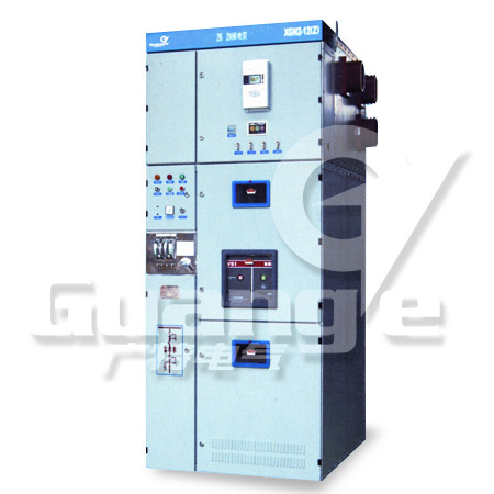
Switchgear Cabinet
| Item No.: | XGN2-12(Z) |

● Standard scheme of cable inlet & outlet and interconnection cabinet for small current switchgear: W 1100×D 1200×H 2650.
● Standard scheme of overhead inlet and outlet wire cabinet for small current switchgear: W1100×D(1200+400)×H2650.
●Standard scheme of cable inlet & outlet and interconnection cabinet for heavy current switchgear: W1100×D1200×H2650.
●Standard scheme of overhead inlet & outlet wire cabinet for heavy current switchgear: W1100×D1200+600×H 2650.
Note;The phase-to-phase spacing is 250mm for current switchgear; and the phase-to-phase spacing is 275mm for heavy current switchgear.
1. With good overall strength and good looking, the switchgear cabinet structure can be altered into full modular type.
2.The cabinet has good compatibility with circuit breakers, and the compatible circuit breakers include the following types: ZN28A, ZN28D, AN65,ZN12,Vep and VD4.
3. Reasonable structure: independent circuit breaker compartment, busbar compartment and relay compartment, which are isolated with steel plates.
4. It adopts mechanical "five-prevention" interlocking mechanism with good safety and reliability.
5. The cabinet body can be maintenance at both sides. From the front side of the cabinet, the secondary components of relay compartment can be inspected. Form the back side of the cabinet, the cable terminals and main busbar can be maintained. Generally, the cabinet is not installed against the wall.
6. With good performance-price ratio, it still enjoys a considerable market share at present.
7. According to the requirement, the cabinet can be installed against the wall.
8. The protection class of the enclosure is IP4X.
Item | Unit | GN30-12(D)/ 1250-40 | GN30-12(D)/ 630-20 | GN30-12(D)/ 100-31.5 | GN30-12(D)/ 2000-50 | GN30-12(D)/ 3150-50 | |||||
Rated voltage of switchgear cabinet | KV | 12 | |||||||||
Lighting impulse withstand voltage(rated insulation level) | KV | 75(ph-ground,ph-ph) 85(Breaker gap) | |||||||||
Rated current) | A | 1250 | 630 | 1000 | 2000 | 3150 | |||||
Rated peak withstand current | KA | 100 | 50 | 80 | 125 | 125 | |||||
Rated short time withstand current(4S) | KA | 40 | 20 | 31.5 | 50 | 50 | |||||
SN | Name | Unit | Technical parameters | ||||||||
1 | Rated voltage | KV | 12 | ||||||||
2 | Rated current | A | 630; 1000;1250;1600;2000;2500;3150 | ||||||||
3 | Rated current of main busbar | A | 630, 1000 | 1000, 2000 | 2500, 3150 | ||||||
4 | Rated insulation level | 1min power-withstand voltage | Ph-ph & Ph-ground | KV | 42 | ||||||
Between open contacts | KV | 48 | |||||||||
Lighting impulse withstanding voltage | Rated short circuit breaking current | KV | 75 | ||||||||
Between open contacts | KV | 85 | |||||||||
5 | Rated short circuit breaking current | KA | 20 | 31.5 | 40 | ||||||
6 | Rated short circuit making current | KA | 50 | 80 | 100 | ||||||
7 | Rated peak withstand current | KA | 50 | 80 | 100 | ||||||
8 | 4S Rated short time withstanding current Rated short time withstanding current | KA | 20 | 31.5 | 40 | ||||||
9 | Breaking times of rated short breaking current | 30 | |||||||||
10 | Mechanical life | 10000(20000-VS1) | |||||||||
11 | 1min power-frequency withstand voltage secondary circuit | KV | 2 | ||||||||
12 | Protection class | IP4X | |||||||||
13 | Busbar system | Single busbar﹑Single busbar with bypass﹑ double-busbar electromagnetic type | |||||||||
14 | Operation mode | Spring energy accumulation type | |||||||||
 English
 Русско
 Deutsch
 Español
 Português
 Français
 Türk
Türk Italiano
 Nederlands
 हिन्दी
 Bahasa Indonesia
